
What Is a CDR? Clock and Data Recovery Explained
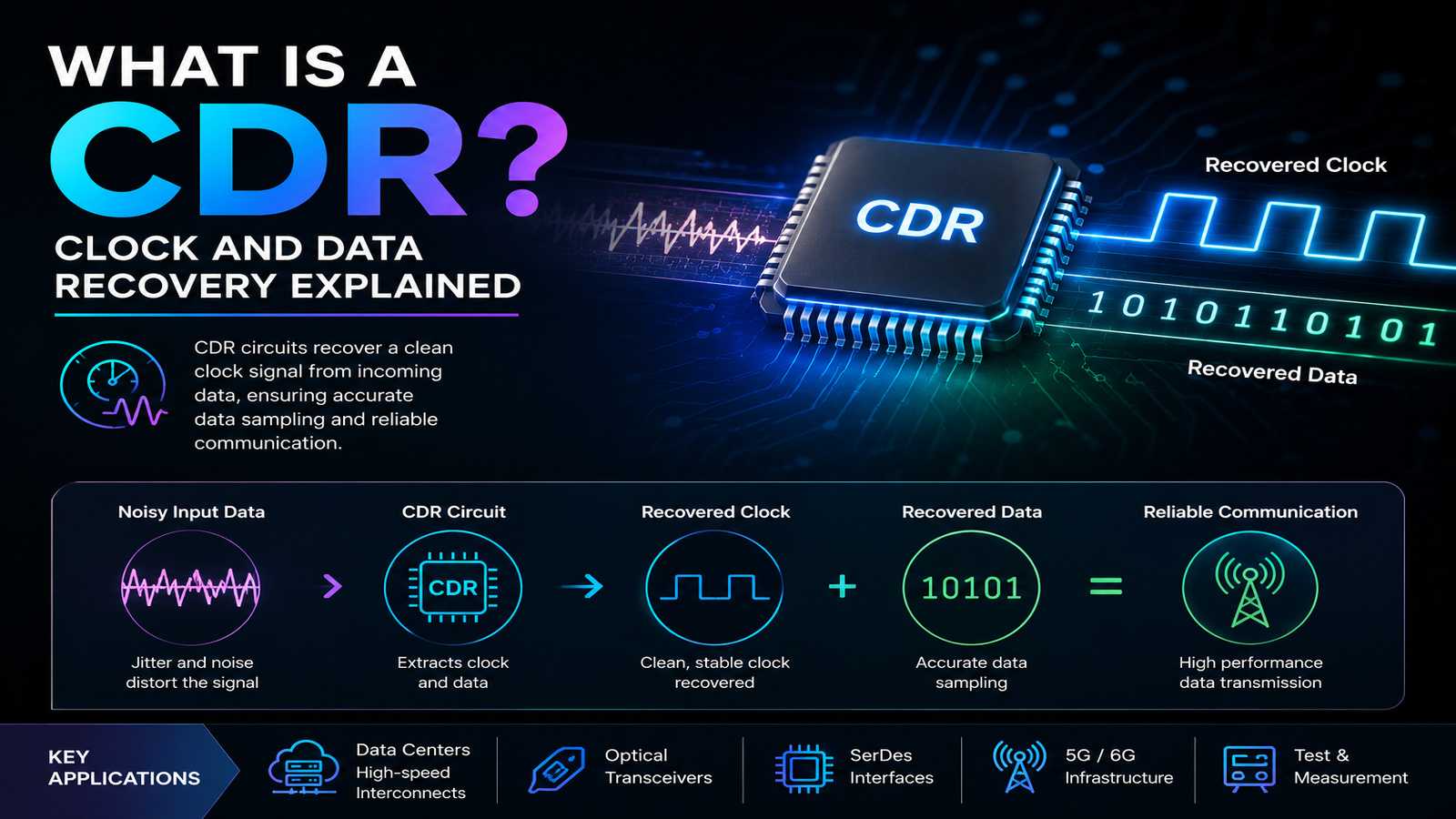
High speed serial links cannot reliably interpret incoming data unless the receiver knows when to sample it. A clock signal is not always transmitted separately, so the receiver has to recover timing information from the data itself.
This is the job of a CDR, or Clock and Data Recovery circuit.
CDRs are a fundamental part of high speed SerDes receivers and are widely used in data center interconnects, networking equipment, optical communication systems, and other high bandwidth applications.
What Is a CDR?
CDR stands for Clock and Data Recovery.
A CDR extracts timing information from an incoming data stream and uses that timing to determine when the receiver should sample the data.
In a high speed serial link, the received signal may contain no dedicated clock line. Instead, transitions within the data provide information that the receiver can use to reconstruct a sampling clock.
A simplified receiver path is:
Incoming data → CDR → recovered clock and data → downstream logic
The challenge is that the incoming signal is rarely ideal. Channel loss, jitter, noise, reflections, and other impairments can shift or distort transitions. The CDR therefore has to recover useful timing despite these limitations.
What Does CDR Mean in SerDes?
In a SerDes receiver, the CDR is responsible for recovering the timing of the serial data stream.
A typical high speed SerDes receiver may contain:
Receiver front end → Equalization → CDR → Deserializer
The exact architecture varies with the application and data rate.
The CDR needs to track changes in the incoming signal while avoiding excessive sensitivity to unwanted timing variations. This creates an important design tradeoff between tracking ability, jitter tolerance, and recovered-clock stability.
How Does Clock and Data Recovery Work?
A CDR generally uses the transitions in an incoming data signal to establish the correct sampling point.
The recovered clock is adjusted according to the timing relationship between the incoming signal and the receiver’s current sampling phase.
Depending on the architecture, a CDR can use techniques involving:
Phase detection
Loop filtering
Voltage controlled oscillators
Phase interpolators
Frequency acquisition
Data sampling
The goal is not simply to generate a clock at the correct frequency. The recovered clock must also place the sampling point where the receiver has sufficient timing margin.
Also Check: What Is SerDes?
Why Is CDR Important in High Speed Communication?
At low data rates, relatively large timing margins can make clock recovery straightforward.
At higher data rates, the available unit interval becomes much smaller. Even a relatively small amount of timing uncertainty can therefore affect the receiver’s ability to distinguish between valid and invalid data.
For example, a high speed link can experience:
Random and deterministic jitter
Channel induced distortion
Inter-symbol interference
Noise
Duty cycle distortion
Reference clock variation
These effects directly influence the timing margin available to the CDR.
This is why CDR design becomes increasingly important as SerDes data rates increase.
CDR and Jitter
Jitter is one of the most important considerations in clock and data recovery.
A receiver does not see perfectly positioned transitions. Their timing can vary from one transition to another.
The CDR has to determine which timing variations should be tracked and which should be rejected.
This is where loop bandwidth becomes important.
A wider loop bandwidth allows the CDR to track faster timing changes, but it can also allow more high frequency jitter to affect the recovered clock.
A narrower bandwidth can filter more timing variation, but may not track slower frequency or phase changes quickly enough.
The correct choice depends on the link architecture and system requirements.
CDR in PAM4 and Modern SerDes
PAM4 increases the number of signal levels from two to four, allowing two bits to be represented by each symbol.
However, the smaller voltage separation between levels makes the receiver more sensitive to noise and signal distortion.
This places additional requirements on the receiver architecture, including its equalization, sampling, clock recovery, and decision circuitry.
As a result, CDR remains an important building block in high speed PAM4-based communication systems.
For systems operating at increasingly high data rates, the CDR cannot be designed independently of the channel and receiver front end. Channel loss, equalization, jitter, and sampling margin all interact with clock recovery performance.
CDR and Signal Integrity
A CDR can only work with the signal that actually reaches the receiver.
If a PCB trace, package, connector, cable, or optical-electrical interface introduces significant distortion, the receiver may see fewer or less well-defined transitions.
This makes signal integrity analysis an important part of high speed CDR development.
Engineers may evaluate the complete channel using simulations, eye diagrams, jitter measurements, and S-parameter models before determining whether the receiver has enough margin.
FMAX Technologies works across high speed mixed signal IC applications where CDR performance has to be considered alongside the transmitter, receiver, channel, and overall system architecture.
Also Read: Signal Integrity
CDR Design Challenges
The practical difficulty in CDR design is balancing several competing requirements rather than optimizing one parameter in isolation.
A high speed CDR may need to provide:
High jitter tolerance
Low recovered-clock jitter
Fast frequency acquisition
Stable operation across process, voltage, and temperature
Low power consumption
Adequate sampling margin
The architecture used to achieve these requirements depends on the data rate, signaling format, process technology, channel characteristics, and system application.
For specialized applications, this can require custom analog and mixed signal design rather than simply selecting a standard receiver component.
FMAX Technologies provides mixed signal IC design capabilities for high speed communication applications, including CDRs, SerDes, PAM4, TIAs, laser drivers, and related high speed analog circuitry.
CDR vs Clock Distribution
A CDR should not be confused with conventional clock distribution.
Clock distribution delivers an existing clock signal through a system while managing skew, timing, and signal quality.
Clock and data recovery generates or reconstructs the timing information from the received data itself.
This distinction becomes particularly important in serial communication systems where transmitting a separate clock would increase the number of required connections and complicate the physical interface.
Also Read: Datacenter Timing IC Solutions
How CDR Fits Into a High Speed Receiver
A CDR is only one part of the receiver.
A practical high speed receiver can involve several stages:
Channel
Receiver front end
Equalization
Clock and data recovery
Data decision
Deserializer
Each stage affects the next.
For example, insufficient equalization can distort the signal before it reaches the CDR. Excessive jitter can reduce the available sampling margin. Poor channel characteristics can make clock recovery more difficult.
This is why high speed receiver design is best approached as a complete signal path rather than as a collection of independent circuit blocks.
FAQs About CDR
A CDR, or Clock and Data Recovery circuit, extracts timing information from an incoming data stream and uses it to recover the clock needed to sample the received data.
CDR stands for Clock and Data Recovery.
In high speed communication systems, CDR refers to circuitry that recovers timing from an incoming serial data stream so the receiver can correctly sample the data.
In SerDes, the CDR is part of the receiver that recovers the timing of the incoming serial signal and provides an appropriate sampling clock for data recovery.
As data rates increase, the available timing margin becomes smaller. CDR helps the receiver establish an accurate sampling point despite jitter, noise, channel loss, and other signal impairments.