
What Is a Limiting Amplifier in an Optical Receiver?
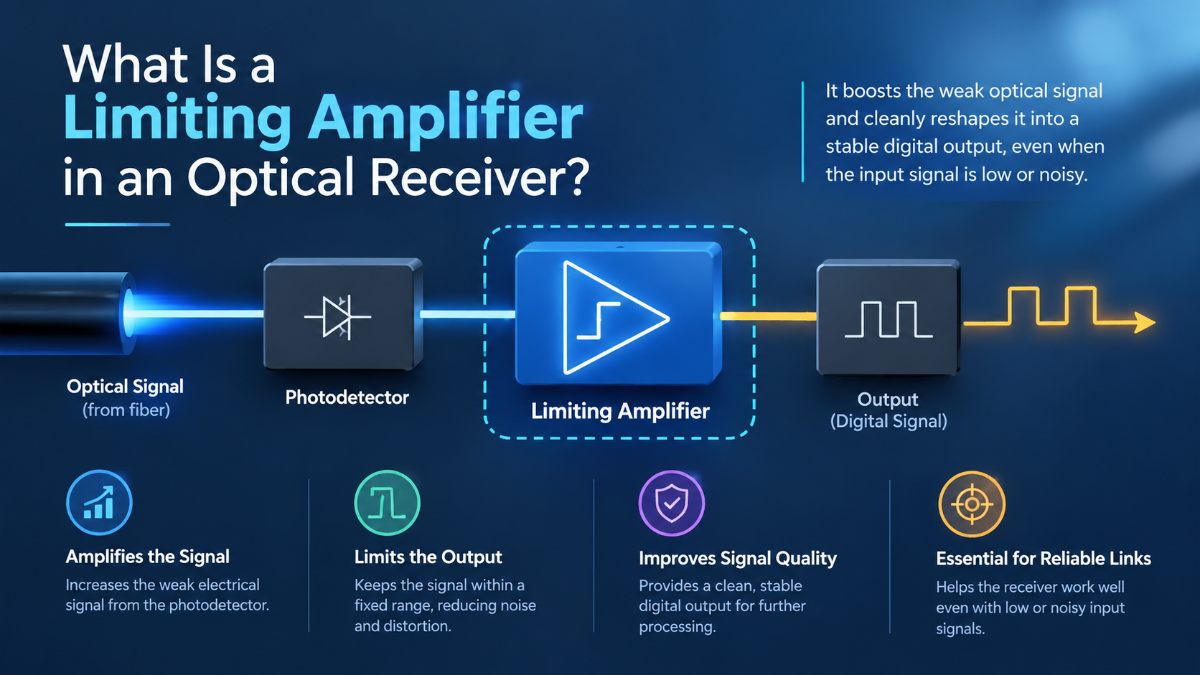
A limiting amplifier is a high-speed amplifier that boosts a received electrical signal and limits its output amplitude to a relatively consistent level. In an optical receiver, it is commonly used after the transimpedance amplifier (TIA) to prepare the signal for subsequent data-processing stages.
The TIA converts the small current generated by a photodiode into a voltage. The limiting amplifier then provides additional gain and produces a more consistent output swing, helping downstream circuitry distinguish the received data.
Limiting amplifiers are used in optical communication systems where receiver signals can vary in amplitude because of changes in received optical power, channel conditions, or preceding circuit stages. Their effectiveness depends on the signal format, bandwidth, noise, and the requirements of the receiver architecture.
How Does a Limiting Amplifier Work?
A limiting amplifier typically consists of high-gain amplifier stages designed to operate at high frequencies. As the input signal increases, the amplifier output approaches its designed voltage limits. Within its operating range, this produces a relatively consistent output amplitude even when the input amplitude changes.
For example, an optical receiver may deliver a small voltage signal from its TIA. The limiting amplifier increases the signal until its output reaches the required swing for the next stage.
This amplitude limiting can reduce the effect of input amplitude variations on the output. However, it does not remove all noise or correct every form of signal distortion. If the input signal has poor signal-to-noise ratio, excessive jitter, or severe distortion, the limiting amplifier cannot reliably reconstruct information that has already been lost.
Its purpose is to amplify and limit the signal, not to replace clock and data recovery or other receiver signal-processing functions.
Where Does It Fit in an Optical Receiver?
In a typical direct-detection optical receiver using a limiting architecture, the main stages include the photodetector, TIA, and limiting amplifier. Further processing may follow, depending on the design.
The photodiode converts incoming light into electrical current. The TIA converts that current into voltage, and the limiting amplifier increases the voltage signal to a suitable output swing.
The exact arrangement varies by receiver design. Some architectures include equalization, additional gain stages, or integrated functions.
For a closer look at the detector interface, see FMAX’s article on what a transimpedance amplifier does in an optical receiver.
Limiting Amplifier vs. Transimpedance Amplifier
Although both circuits amplify signals, they perform different jobs.
|
Feature |
Transimpedance amplifier (TIA) |
Limiting amplifier |
|---|---|---|
|
Main function |
Converts photodiode current into voltage |
Amplifies a voltage signal and limits output amplitude |
|
Typical position |
Near the photodiode |
Usually downstream of the TIA |
|
Key design concerns |
Input-referred noise, transimpedance gain, bandwidth and detector capacitance |
Gain, bandwidth, output swing, noise and signal integrity |
|
Output behavior |
Voltage depends on input current and circuit gain |
Output amplitude becomes relatively constant over the limiting range |
|
Main role |
Detect and amplify the photodiode signal |
Prepare the electrical signal for subsequent receiver stages |
The two circuits complement each other. A limiting amplifier cannot replace the TIA because the photodiode produces current, and the receiver needs an appropriate current-to-voltage interface.
What Matters When Selecting a Limiting Amplifier?
The right limiting amplifier depends on the optical receiver’s data rate, signal format, input range, and output requirements. Several specifications deserve attention.
Bandwidth: The amplifier must support the signal’s required frequency content. Insufficient bandwidth can close the eye opening and introduce intersymbol interference.
Gain and limiting range: The available gain must be sufficient for the expected input signal range. Engineers should check the input level at which limiting begins and the output swing delivered under specified conditions.
Input sensitivity and noise: A limiting amplifier cannot reliably distinguish data when the incoming signal is buried in noise. Sensitivity depends on the complete receiver, including the photodetector, TIA, and limiting stage.
Jitter and edge quality: Amplifier noise and nonlinear behavior can affect output transitions. The design must meet the receiver’s timing and signal-integrity requirements.
Output interface: Output amplitude, common-mode level, loading, and interface type must match the next stage.
Power consumption: High-speed amplifiers can contribute significantly to the power budget of an optical module, making power and thermal limits important design constraints.
Specifications should be evaluated together rather than in isolation. A wide bandwidth, for example, does not guarantee good receiver performance if noise, jitter, or input sensitivity is inadequate.
Limiting Amplifiers and Different Signal Formats
A conventional limiting amplifier is commonly associated with binary signalling, where the receiver needs to distinguish between two logical states. Limiting the output amplitude can help provide a consistent signal to subsequent digital circuitry.
Multilevel formats such as PAM4 require more care. PAM4 represents data using four signal levels, so indiscriminately limiting the waveform can destroy the amplitude distinctions needed to decode the symbols. These systems generally require an appropriate linear signal path and receiver architecture rather than treating a conventional limiting amplifier as a universal solution.
The choice of amplifier therefore depends on the modulation format and the role of the circuit within the receiver.
Why Limiting Amplifier Design Matters in High-Speed Optical Links
At high data rates, the limiting amplifier operates as part of a connected signal path. Its performance depends on the quality of the signal arriving from the TIA, the amplifier’s own frequency response and noise, and the electrical interface to the following circuit.
Designers must consider gain distribution, parasitic capacitance, layout, loading, power consumption, and behavior across operating conditions. The amplifier also needs to work within the receiver’s overall signal and timing budgets.
FMAX Technologies works on high-speed analog and mixed-signal ICs for optical communication systems. Its optical interconnect IC solutions cover related building blocks, including TIAs, laser drivers, clock and data recovery ICs, and high-speed limiting amplifiers.
For projects that require a custom analog or mixed-signal circuit, FMAX’s IC design services are relevant when the receiver’s performance, integration, or interface requirements call for a custom design.
FAQs About Limiting Amplifiers in Optical Receivers
It amplifies the electrical signal received from an earlier stage and limits its output amplitude over a specified input range. This helps provide a more consistent signal level for subsequent receiver circuitry.
No. A TIA converts photodiode current into voltage. A limiting amplifier operates on a voltage signal and provides further gain with amplitude limiting.
No. It may reduce the effect of input amplitude variations on the output, but it does not eliminate noise. Noise that affects the ability to distinguish data can still cause errors and timing uncertainty.
It depends on the architecture. A conventional limiting amplifier can destroy the distinctions between PAM4's four amplitude levels. PAM4 receivers need a signal path designed to preserve and process those levels appropriately.
Important factors include bandwidth, gain, input sensitivity, noise, limiting range, output swing, jitter performance, power consumption, and compatibility with the following circuit stage.