

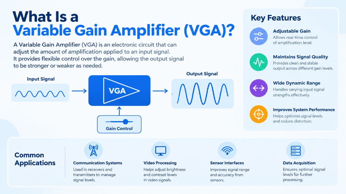
What Is a Variable Gain Amplifier (VGA)?
A variable gain amplifier (VGA) is an electronic circuit that changes its amplification level in response to a control signal. It allows a system to handle input signals of different strengths without requiring a fixed-gain amplifier to be replaced or the signal path to be redesigned.
VGAs are used in RF receivers, wireless communication systems, radar, test instrumentation, and other applications where signal amplitude can vary considerably. They are particularly useful when a signal must be amplified enough for accurate processing without overloading the next stage.
For engineers designing high-speed analog and mixed-signal systems, selecting a VGA involves more than choosing a gain range. Bandwidth, noise, linearity, gain accuracy, and settling time all affect how well the circuit performs in its intended application.
How Does a Variable Gain Amplifier Work?
A VGA amplifies an input signal while allowing its gain to be adjusted through an analog control voltage or a digital control setting, depending on the design.
Consider a receiver that processes signals arriving at different power levels. A weak signal may need substantial amplification before it reaches the analog-to-digital converter (ADC). A stronger signal may require less gain to avoid clipping or distortion.
The VGA adjusts its gain to accommodate these changes.
In a typical implementation, the input signal passes through an amplification stage whose effective gain depends on the control setting. The circuit may vary the transconductance of its active devices, adjust an attenuation network, or combine variable attenuation with fixed-gain amplification.
The relationship between the control signal and the resulting gain depends on the circuit design. Some VGAs provide continuous adjustment, while digitally controlled versions offer discrete gain steps.
Understanding VGA Gain
Voltage gain is the ratio between output voltage and input voltage:
[
A_v=\frac{V_{\text{out}}}{V_{\text{in}}}
]
Gain is also commonly expressed in decibels (dB):
[
G_{\text{dB}}=20\log_{10}|A_v|
]
For example, an ideal amplifier with a voltage gain of 10 has a gain of 20 dB. If the input is 100 mV, the output would be 1 V, assuming the amplifier operates within its specified linear range and the load does not alter the result.
A VGA changes this gain according to its control setting. Its gain range describes the difference between the lowest and highest available gain, while its gain-control characteristic describes how the gain changes as the control input changes.
Some devices use a linear-in-dB control relationship, which can simplify gain adjustment across a wide range.
What Is the Role of a VGA in Automatic Gain Control?
Automatic gain control (AGC) is a feedback technique that adjusts amplification to keep a signal near a desired output level. A VGA is often the adjustable-gain element within an AGC system.
The system measures the output signal level and compares it with a target. If the signal is too weak, the controller increases gain. If the signal becomes too strong, it reduces gain.
For example, a wireless receiver may receive a strong signal when a transmitter is nearby and a much weaker signal when the transmitter moves farther away or the propagation conditions change. AGC helps the receiver accommodate these variations.
The VGA does not perform the entire control function by itself. The detector, controller, timing behavior, and gain-control response all influence how the system reacts to changes in signal strength.
An AGC loop that responds too slowly may struggle with rapid changes. One that responds too aggressively may introduce unwanted gain fluctuations or interact with the modulation of the signal.
Where Are Variable Gain Amplifiers Used?
RF and wireless communication receivers
Received signal strength can vary with distance, interference, and propagation conditions. VGAs help adjust signal levels at RF, intermediate-frequency (IF), or baseband stages, depending on the receiver architecture.
The gain must be sufficient to process weak signals while maintaining acceptable noise and distortion performance when stronger signals are present.
High-speed data acquisition
In measurement systems, the amplitude of the input signal may vary between measurements or operating conditions. A VGA can scale the signal to make effective use of the ADC’s input range.
The design must account for the ADC’s full-scale input, bandwidth, noise, and settling requirements. Increasing gain does not recover information already lost to noise, and excessive gain can cause clipping.
Radar and instrumentation
Radar receivers process reflected signals that can differ substantially in amplitude. VGAs can adjust receiver sensitivity and help manage the range of signal levels presented to subsequent processing stages.
In electronic test equipment, adjustable gain can also support measurements across different input ranges without changing the entire analog front end.
Ultrasound and sensor systems
Some imaging systems use variable gain to compensate for signal attenuation. In ultrasound, time-gain compensation increases amplification for later-arriving echoes, which often have traveled farther through tissue and have weakened.
The gain may be programmed as a function of time rather than controlled solely by the instantaneous signal amplitude.
Key Specifications to Check When Selecting a VGA
The correct VGA depends on the complete signal chain. These specifications deserve particular attention.
Gain range: The available minimum and maximum gain determine the range of input amplitudes the system can accommodate. Check whether the gain is continuously adjustable or available in fixed steps.
Bandwidth: The amplifier must handle the required signal frequencies without unacceptable attenuation or distortion. A gain specification measured at low frequency does not establish performance at higher frequencies.
Noise figure and input-referred noise: Noise affects the ability to detect weak signals. In receiver applications, the VGA’s position relative to other stages matters because noise added early in the signal chain can have a greater effect on overall sensitivity.
Linearity and distortion: Strong input signals can cause compression or generate unwanted frequency components. Parameters such as input or output third-order intercept point (IIP3 or OIP3), along with compression specifications, help characterize performance under larger signals.
Gain-control accuracy: The actual gain may differ from the ideal control curve because of process variation, temperature, frequency, and supply voltage. A predictable gain-control characteristic can simplify system calibration.
Settling time: After a gain change, the output needs time to settle within the required error band. This matters in systems that switch gain between measurements or respond to rapidly changing signal levels.
Power consumption and interfaces: Supply voltage, current consumption, input and output impedance, and compatibility with adjacent stages affect the practical choice of device or circuit architecture.
These specifications interact. A wide gain range is not useful if noise becomes unacceptable at high gain or distortion becomes excessive at low attenuation. Engineers should evaluate performance across the intended operating conditions rather than relying on a single headline specification.
What Matters When Designing a Custom VGA IC?
A custom VGA may be appropriate when standard components cannot meet the required combination of bandwidth, gain range, noise, linearity, power consumption, and integration constraints.
The design begins with the application requirements and the expected signal range. Engineers then determine the gain-control approach, circuit architecture, interfaces, and operating conditions.
Verification should cover the full gain range, including gain flatness, distortion, noise, control response, and performance across process, voltage, and temperature variations. The interface with the ADC or the next amplifier stage must also be considered because loading and impedance mismatches can affect the result.
For high-speed applications, parasitic capacitance, interconnect effects, and layout can influence bandwidth and stability. These effects need attention during circuit design and physical implementation, not only during final testing.
FMAX Technologies develops custom analog ICs and offers commercial ICs for high-speed data-center timing, clocking, and test instrumentation. Its product catalog includes the FX2100A Variable Gain Amplifier, which provides a relevant starting point for engineers investigating VGA devices.
You can review the FMAX product catalog or explore its IC design services if your project requires a custom analog or mixed-signal circuit.
What Is a Variable Gain Amplifier (VGA)
A fixed-gain amplifier provides a set amplification level under specified operating conditions. A VGA allows the gain to change through a control signal, making it suitable for systems that must accommodate varying input amplitudes.
No. A VGA is an amplifier with adjustable gain. AGC is a control system that adjusts gain based on a measured signal level. An AGC system often uses a VGA, along with a detector and control circuitry.
A dB-linear VGA has a gain-control relationship that is approximately linear when gain is expressed in decibels. This means equal changes in the control input produce approximately equal changes in gain in dB over the specified range.
A VGA can scale an input signal to make better use of an ADC's available input range. However, it cannot eliminate existing noise or restore information lost through distortion, clipping, or insufficient bandwidth. The VGA and ADC must be designed to work together.
A custom design may be worth evaluating when the required bandwidth, gain range, noise, linearity, power consumption, or interface requirements cannot be met by available components. The decision should be based on system-level specifications and implementation constraints.