
What Is a Time Domain Reflectometer (TDR)
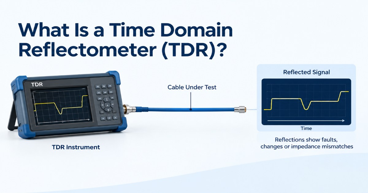
A Time Domain Reflectometer (TDR) is a test instrument or circuit used to locate impedance changes along a transmission line. It sends a fast electrical signal into the line and measures the signal that returns when part of the energy is reflected by an impedance discontinuity.
The timing of the reflection indicates where the discontinuity is located. Its amplitude and polarity provide information about the type and severity of the impedance change.
TDRs are used for cable testing, PCB and connector characterization, transmission-line measurements, and precision test instrumentation.
How Does a Time Domain Reflectometer Work?
A TDR relies on a simple measurement principle: a uniform transmission line produces little or no reflection, while a change in impedance produces a reflected signal.
The instrument applies a known electrical stimulus to the transmission line and monitors the returning waveform. Because the signal travels to the discontinuity and back, the measured round-trip time can be used to calculate its distance.
A simplified relationship is:
Distance = propagation velocity × round-trip time / 2
The propagation velocity depends on the electrical characteristics of the transmission line. Using the correct velocity is therefore important when converting measured time into physical distance.
For example, an open circuit and a short circuit produce reflections with different polarity, while a connector or cable transition may produce a smaller localized reflection.
What Does a TDR Measure?
A TDR primarily measures changes in impedance as a function of time.
From the reflected waveform, engineers can determine:
-
Location of an impedance discontinuity
-
Magnitude of the reflection
-
Reflection polarity
-
Approximate impedance change
-
Distance between multiple discontinuities
This makes TDR useful when a conventional continuity measurement is not enough. A continuity test may indicate that a connection is electrically present, but it cannot normally show where a localized impedance problem occurs.
What Can a TDR Detect?
The type of discontinuity depends on the system being tested. Common examples include:
-
Open and short circuits
-
Connector discontinuities
-
Cable faults
-
Splices and terminations
-
Changes in transmission-line impedance
-
PCB trace discontinuities
-
Manufacturing or assembly defects
In high-speed systems, even a small discontinuity can affect signal integrity. Connectors, packages, vias and PCB transitions can introduce reflections that become more significant as signal rise times decrease.
Read: Linear Pluggable Optics IC
What Determines TDR Resolution?
TDR resolution is closely related to the speed of the electrical stimulus.
A faster edge contains more high-frequency content and allows closely spaced discontinuities to be distinguished more effectively. A slower edge spreads the response over a longer time interval, making nearby events harder to separate.
TDR performance is therefore influenced by:
-
Signal rise time
-
Analog bandwidth
-
Sampling bandwidth
-
Timing accuracy
-
Signal-to-noise ratio
-
Input and package capacitance
-
Transmission-line characteristics
There is also a practical trade-off between measurement range and resolution. A TDR architecture has to capture a sufficiently large portion of the reflected signal while preserving the bandwidth needed to resolve small or closely spaced events.
Also Read: Chip Design for Optical Transceivers
Why Is High-Speed TDR IC Design Difficult?
The challenge is not simply generating a fast signal. The measurement circuitry must also capture the returning waveform without significantly changing it.
At high bandwidths, the TDR signal path is affected by device parasitics, package interconnects, input capacitance, PCB routing and termination. The sampling circuit must maintain sufficient bandwidth and timing accuracy while keeping noise and distortion low.
This is where the analog front end becomes critical.
A TDR IC may combine a fast step generator with a high-bandwidth sample-and-hold circuit to generate the stimulus and capture the reflected waveform. The quality of both functions directly affects the measurement.
FMAX develops TDR and Sample & Hold ICs for precision test and measurement applications, including integrated architectures designed for high-speed signal generation and sampling.
TDR in Test and Measurement Systems
Modern test equipment often needs to measure much faster electrical events than traditional cable fault testing requires.
Applications can include:
-
Transmission-line characterization
-
PCB and connector testing
-
Digital sampling oscilloscopes
-
Automated test equipment
-
High-speed communications testing
-
Handheld test instrumentation
In these systems, the TDR front end has to fit within the instrument’s bandwidth, noise, power and sampling requirements.
FMAX’s TDR IC portfolio includes devices that integrate TDR step generation and high-bandwidth Sample & Hold circuitry for instrumentation applications. Its FX366C, for example, combines a 30 GHz TDR and Sample & Hold architecture with an 8 ps TDR edge and sub-1 mVrms input-referred noise.
TDR and High-Bandwidth Sample & Hold
A fast TDR stimulus is only useful if the reflected waveform can be captured accurately.
A high-bandwidth Sample & Hold circuit allows the measurement system to sample a rapidly changing analog waveform at a precise point in time and hold that value for subsequent processing. Bandwidth, noise, aperture performance and settling behavior all affect the quality of the captured waveform.
This is why TDR and Sample & Hold functions are often closely connected in high-speed instrumentation IC design.
For a deeper look at this relationship, see FMAX’s article on
TDR IC and High Bandwidth Sample & Hold Amplifiers in Test Instrumentation.
TDR vs OTDR
TDR and Optical Time Domain Reflectometry (OTDR) use a similar measurement concept but operate on different physical media.
A TDR measures electrical transmission lines using an electrical stimulus and its reflections. An OTDR uses optical pulses to analyze reflections and scattering along an optical fiber.
The underlying idea is similar: the timing of returned energy provides information about where an event occurs. The devices, signal paths and measurement requirements are different.
FAQs: FAQs: What Is a Time Domain Reflectometer
A time domain reflectometer is a test instrument or IC that uses signal reflections to identify impedance changes along a transmission line and determine their location.
Time domain reflectometry is used to locate cable faults, characterize transmission lines, identify connector and PCB discontinuities, and analyze impedance changes in high-speed electrical systems.
A TDR sends a known electrical signal into the cable and measures the returning reflection. The round-trip time indicates the location of the fault, while the reflection characteristics provide information about the discontinuity.
Signal rise time, analog bandwidth, sampling performance, timing accuracy, noise and transmission-line characteristics all affect TDR resolution.
A TDR measures electrical transmission lines, while an OTDR measures optical fiber. Both use the timing of returned energy to locate events along the medium.