
Signal Integrity: What It Is and Why It Matters in High-Speed Digital Systems
As digital systems move to higher data rates, the electrical path between a transmitter and receiver becomes increasingly difficult to treat as a simple wire.
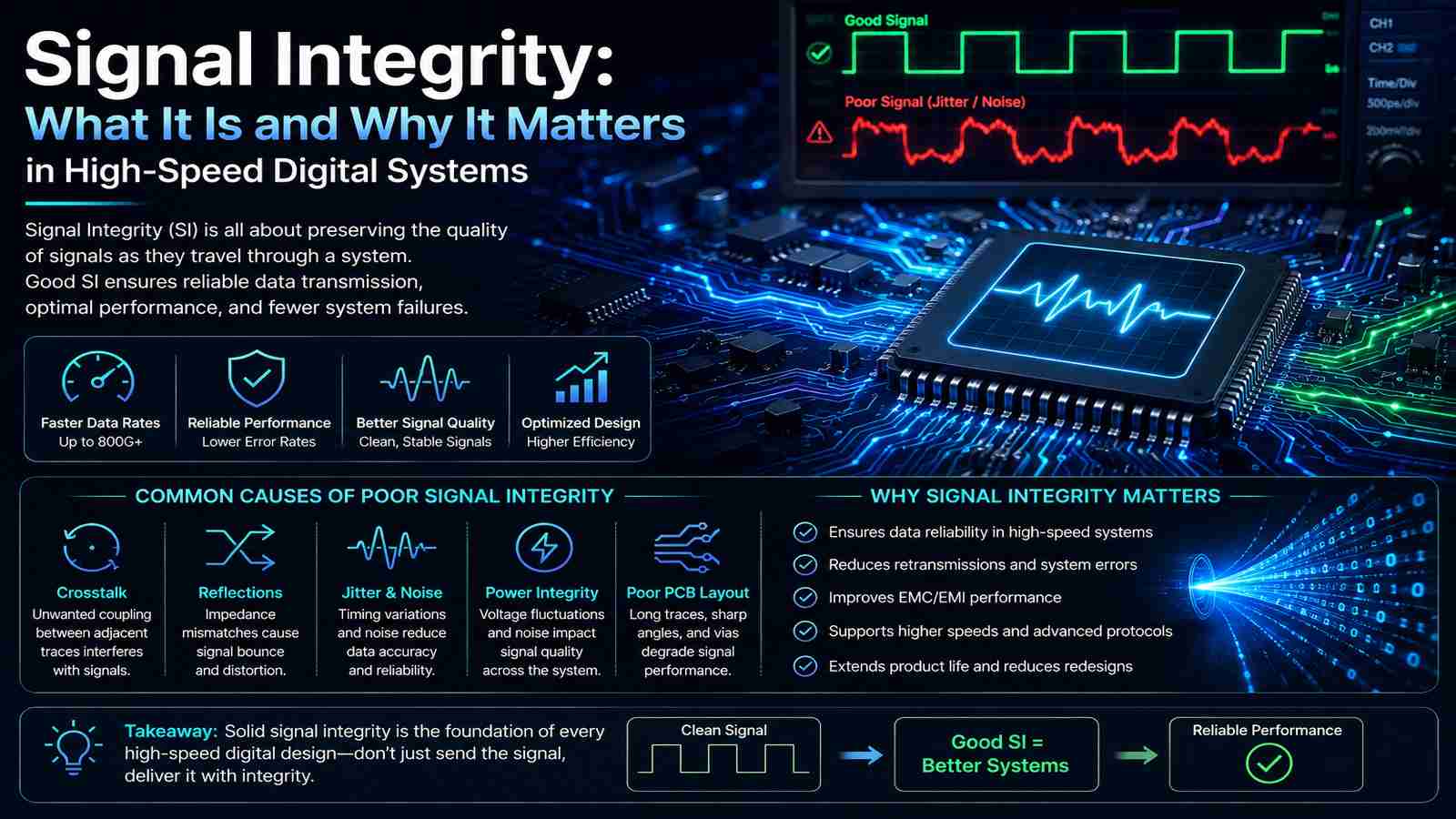
PCB traces, packages, connectors, vias, cables, and IC interfaces all affect the signal. Loss, reflections, crosstalk, jitter, and impedance discontinuities can distort the waveform before it reaches the receiver.
This is where signal integrity becomes critical.
Signal integrity is the practice of maintaining enough signal quality and timing margin across a high-speed channel for the receiver to reliably recover the transmitted data.
What Is Signal Integrity?
Signal integrity (SI) describes how well an electrical signal maintains its required voltage, timing, and waveform characteristics as it travels through a physical interconnect.
In a low-speed digital circuit, a PCB trace can often be treated approximately as a wire. At higher data rates, that assumption breaks down. The trace becomes a transmission line, and its physical characteristics begin to influence the signal.
A high-speed channel may include:
-
Transmitter IC
-
IC package
-
PCB traces
-
Vias
-
Connectors
-
Cables or backplanes
-
Receiver package
-
Receiver IC
Each element can introduce some amount of loss, reflection, coupling, or timing variation.
The goal of signal-integrity engineering is therefore not to produce a theoretically perfect waveform. It is to ensure that the complete channel provides enough margin for reliable operation.
Why Signal Integrity Matters in High-Speed Digital Systems
Higher data rates leave less time for a receiver to distinguish between consecutive symbols.
As signaling speeds increase, several effects become more significant:
-
Insertion loss reduces high-frequency signal content.
-
Reflections distort the waveform when impedance changes occur.
-
Crosstalk couples energy between adjacent channels.
-
Jitter shifts signal transitions in time.
-
Inter-symbol interference (ISI) causes one symbol to influence another.
-
Power-supply noise can affect analog and timing circuits.
A channel that works reliably at one data rate may therefore require additional signal conditioning or a different architecture when the data rate increases.
This is particularly important in high-speed SerDes, data-center interconnects, optical modules, and PAM4-based systems.
What Causes Signal Integrity Problems?
Signal-integrity problems usually result from the combined behavior of the channel rather than one isolated component.
Insertion Loss
Every practical interconnect introduces some loss. PCB copper, dielectric materials, connectors, cables, and packages can attenuate the signal, particularly at higher frequencies.
Excessive channel loss can reduce signal amplitude and increase inter-symbol interference, making it harder for the receiver to recover the data.
Reflections and Impedance Discontinuities
When a signal encounters a change in impedance, part of its energy can be reflected toward the source.
Discontinuities can occur at:
-
Vias
-
Connectors
-
Package transitions
-
Trace-width changes
-
Poorly controlled transmission lines
Maintaining the intended characteristic impedance throughout the channel helps reduce these reflections.
Crosstalk
Closely spaced high-speed traces can couple electromagnetic energy into one another.
Crosstalk becomes more problematic when traces run in parallel for longer distances or when signal edges become faster.
The resulting unwanted signal can reduce noise margin and contribute to timing errors.
Jitter
Jitter is the variation in the timing of signal transitions from their expected positions.
It can originate from clock sources, power-supply noise, crosstalk, reflections, PLLs, or the channel itself.
In high-speed links, excessive jitter reduces the available timing margin at the receiver.
FMAX has also examined common sources of jitter in high-speed communication systems, including reflections, impedance mismatch, crosstalk, and power-related effects.
Common Causes of Jitter in High-Speed Communication Systems
Inter-Symbol Interference
Inter-symbol interference (ISI) occurs when the signal associated with one symbol extends into the time period of another.
Channel loss and dispersion can spread signal transitions over time. At high data rates, this overlap can significantly reduce the receiver’s ability to distinguish between symbols.
Signal Integrity Analysis: What Engineers Evaluate
Signal integrity analysis examines whether a high-speed channel can meet its electrical and timing requirements.
Depending on the application, engineers may evaluate:
-
Channel insertion loss
-
Return loss
-
Impedance
-
Crosstalk
-
Jitter
-
Eye opening
-
Bit-error performance
-
Equalization requirements
An eye diagram is one of the most useful visual methods for evaluating high-speed signal quality. A progressively smaller eye opening can indicate that noise, jitter, ISI, loss, or other impairments are consuming the available margin.
Signal-integrity analysis can combine simulation with physical measurement. Simulation helps identify problems before hardware is built, while measurements validate whether the actual hardware behaves as expected.
For complex high-speed designs, the objective is to correlate the two rather than rely exclusively on either one.
Signal Integrity Simulation and S-Parameters
Signal integrity simulation allows engineers to model how a signal will behave across a proposed channel before committing to hardware.
Models can include PCB traces, packages, connectors, cables, and IC characteristics.
For high-frequency channels, engineers commonly use S-parameters to describe how a network transmits and reflects signals.
For example:
-
S21 describes forward transmission through a two-port network.
-
S11 describes input reflection.
-
S22 describes output reflection.
These models can be incorporated into channel simulations to understand how individual components contribute to overall signal quality.
The value of simulation is greatest when the models accurately represent the physical design. An idealized channel model cannot reveal problems caused by an incorrectly modeled package, connector, via structure, or PCB stack-up.
Signal Integrity in SerDes and PAM4 Systems
Signal integrity becomes particularly demanding in high-speed SerDes systems because data must travel through bandwidth-limited electrical channels at very high symbol rates.
The complete path can extend from a transmitter through the package, PCB, connector, cable or backplane, and finally into the receiver.
Equalization, clock and data recovery, redrivers, and other signal-conditioning techniques may be required to compensate for channel limitations.
PAM4 introduces another challenge. Instead of two voltage levels, PAM4 uses four. This allows more bits to be transmitted per symbol, but the smaller voltage separation between levels reduces vertical noise margin.
As a result, PAM4 links are particularly sensitive to channel loss, jitter, crosstalk, and other signal-integrity impairments.
FMAX’s high-speed mixed-signal capabilities include PAM4, CDR, SerDes, TIA, and other IC technologies used in high-speed communication systems.
FMAX’s existing analysis of PAM4 vs NRZ provides additional context on the trade-offs between the two signaling methods.
Signal and Power Integrity Are Closely Connected
Signal integrity and power integrity are different engineering disciplines, but they interact closely in high-speed systems.
A high-speed IC can produce rapidly changing current demands. If the power-distribution network allows excessive voltage variation, that noise can affect sensitive analog, clock, transmitter, or receiver circuits.
This can ultimately appear as degraded signal quality or increased timing uncertainty.
For that reason, signal and power integrity often need to be considered together when developing demanding high-speed hardware.
When Signal Integrity Becomes an IC Design Problem
Not every signal-integrity problem can be solved by changing the PCB.
At higher data rates, the IC itself becomes an important part of the channel. Transmitter output stages, receiver front ends, equalizers, CDRs, PLLs, TIAs, and package interfaces all influence the final signal.
A board-level redesign may not be enough when the fundamental limitation is inside the silicon.
This is where custom mixed-signal IC design can become important. FMAX Technologies develops high-speed analog and mixed-signal ICs for applications including datacenter interconnects, optical communications, and precision instrumentation, with capabilities spanning CDRs, SerDes, TIAs, PAM4, TDRs, and high-bandwidth sample-and-hold circuits.
How to Approach Signal Integrity in a High-Speed Design
A practical signal-integrity process should begin before the PCB is finalized.
Engineers typically need to:
-
Define the data-rate and channel requirements.
-
Establish the allowable loss and timing margins.
-
Model the complete signal path.
-
Identify impedance discontinuities and coupling risks.
-
Simulate the channel under expected operating conditions.
-
Measure the hardware and compare it with the model.
-
Determine whether the limitation is in the interconnect, package, or IC.
-
Apply the appropriate channel or silicon-level solution.
This approach is more effective than treating signal integrity as a final-stage debugging exercise.
For high-speed systems, signal integrity is a system-design consideration. The PCB, package, IC, connector, power network, and receiver architecture all contribute to the final result.
FAQs About Signal Integrity
Signal integrity is the ability of a high-speed electrical signal to maintain sufficient voltage and timing quality across its physical channel so that the receiver can reliably recover the transmitted data.
Signal integrity analysis evaluates the effects of channel characteristics such as insertion loss, reflections, crosstalk, impedance discontinuities, jitter, and ISI on high-speed signal performance.
Signal integrity simulation uses electrical models of components and interconnects to predict how signals will behave before or alongside physical hardware testing.
PAM4 uses four voltage levels, which increases data efficiency but reduces the voltage separation between adjacent levels. This makes PAM4 more sensitive to noise, jitter, crosstalk, and channel distortion.
Signal integrity focuses on the behavior of signal paths, while power integrity focuses on the behavior of power-delivery networks. They interact because power-supply noise can affect high-speed signal and timing performance.