

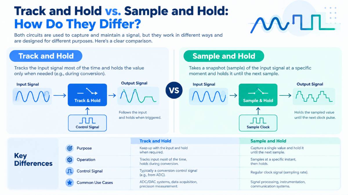
Track and Hold vs. Sample and Hold: How Do They Differ?
Track-and-hold and sample-and-hold circuits help electronic systems capture an analog signal and keep its voltage stable for measurement or conversion. They are used in data acquisition, analog-to-digital conversion, oscilloscopes, and high-speed test instrumentation.
The terms are closely related, and in many circuits, they describe the same basic operation. The distinction often comes down to how the circuit is used: a track-and-hold circuit follows the input for most of its operating cycle and holds it briefly, while a sample-and-hold circuit is commonly described in terms of capturing a value and retaining it for a longer interval.
For engineers selecting a circuit for high-speed instrumentation or designing a custom analog IC, the operating mode is only part of the decision. Input bandwidth, aperture jitter, acquisition time, noise, and hold-mode behavior also affect measurement accuracy.
What Is a Track-and-Hold Circuit?
A track-and-hold (T/H) circuit follows a changing analog input during its track phase. When the control signal switches the circuit into hold mode, the output retains the voltage corresponding to the input at the sampling instant, subject to the circuit’s timing and settling errors.
During tracking, the circuit responds to changes in the input signal. During holding, it attempts to maintain the captured voltage long enough for a downstream circuit to use it.
Track-and-hold circuits are useful when a system needs to capture a rapidly changing signal at a defined point in time. They are found in high-speed data acquisition systems, ADC front ends, and precision measurement equipment.
Their performance depends on how faithfully the circuit follows the input and how accurately it captures the signal when the hold command arrives.
What Is a Sample-and-Hold Circuit?
A sample-and-hold (S/H) circuit captures the instantaneous value of an analog signal and holds that value for a specified period.
A basic implementation uses a sampling switch, a hold capacitor, and often a buffer amplifier. During the sampling phase, the switch allows the capacitor to charge toward the input voltage. When the switch opens, the capacitor retains its charge, providing a relatively stable output for the next stage.
The hold voltage is not perfectly constant in a real circuit. Leakage, switching transients, charge injection, and other non-ideal effects can cause the output to deviate from the captured value.
Sample-and-hold circuits are widely used ahead of analog-to-digital converters, in data acquisition systems, and in sampling oscilloscopes. They give the conversion or measurement stage a defined voltage to work with rather than requiring it to follow a continuously changing input.
Track and Hold vs. Sample and Hold: Key Differences
|
Feature |
Track and Hold |
Sample and Hold |
|---|---|---|
|
Operating emphasis |
Follows the input during most of the cycle |
Captures a value and retains it for the required interval |
|
Track or sample phase |
Output follows the changing input |
Circuit acquires the input value |
|
Hold phase |
Output retains the captured value |
Output retains the captured value |
|
Typical use |
High-speed signal acquisition and ADC front ends |
ADC input stabilization and data acquisition |
|
Important design factors |
Tracking bandwidth, capture timing, jitter and settling |
Acquisition time, hold accuracy, droop and switching errors |
These are differences in emphasis rather than a strict division between two unrelated circuit architectures. A well-designed sample-and-hold circuit also tracks the input before the hold command, and many engineering references use the two terms interchangeably.
The application, circuit implementation, and timing requirements determine which name is used.
How the Two Circuits Work in an ADC System
An ADC converts an analog voltage into a digital representation. If its input changes while the converter is processing a measurement, the result may not represent the intended input value.
A track-and-hold or sample-and-hold stage addresses this problem by capturing the signal and maintaining a sufficiently stable voltage during the required conversion interval.
Consider a measurement system monitoring a fast electrical pulse. The input may change substantially over a short period. The sampling circuit must capture the relevant voltage at the correct time, then hold it while the conversion stage processes the measurement.
The sampling circuit does not remove errors already present in the signal. If its bandwidth is insufficient, its noise is too high, or the sampling instant is uncertain, the captured value may already be inaccurate.
This is why the performance of the sampling front end matters alongside the ADC’s resolution and conversion speed.
Which Performance Parameters Matter Most?
The choice between track-and-hold and sample-and-hold should follow the application’s electrical and timing requirements, not the circuit name alone.
Input bandwidth
Bandwidth determines how well the circuit responds to the frequency components of the input signal. A circuit intended for high-speed instrumentation may need to capture signals with frequency content far beyond the ADC’s sampling clock frequency, particularly in equivalent-time sampling or subsampling applications.
The required bandwidth depends on the signal spectrum, measurement method, and acceptable distortion. A higher bandwidth rating alone does not guarantee accurate measurements.
Acquisition time and settling
Acquisition time is the interval needed for the circuit to reach the required accuracy after entering its tracking or sampling state. Settling behavior describes how quickly the output reaches and stays within the specified error band following a transition.
Insufficient acquisition time can leave the hold capacitor or output short of the correct input value when the next sample is taken.
Aperture time and aperture jitter
Aperture time describes the effective interval associated with the transition from tracking to holding. Aperture delay is the timing offset between the control edge and the effective sampling instant.
Aperture jitter is the variation in that timing from sample to sample. When the input changes rapidly, even a small timing error can translate into a significant voltage error.
For a sinusoidal input, the approximate signal-to-noise ratio limit caused by sampling-clock jitter is:
SNR = −20 log₁₀(2πf₍in₎t₍j₎)
Here, f₍in₎ is the input frequency and t₍j₎ is the RMS sampling-time jitter. This relationship assumes that jitter is the dominant error source and is uncorrelated with the input signal.
It shows why timing quality becomes increasingly important as the input frequency rises.
Hold-mode accuracy and noise
During the hold phase, the output should remain close to the captured voltage. Leakage causes droop over time, while switch charge injection and clock feedthrough can introduce a voltage step when the circuit changes modes.
Noise and distortion also affect the smallest signal changes that the measurement system can resolve. Engineers should evaluate these parameters under the intended input frequency, signal amplitude, sampling rate, and hold duration.
Where Are Track-and-Hold and Sample-and-Hold Circuits Used?
Both circuit types support applications that require accurate measurements of time-varying signals.
Digital sampling oscilloscopes: Sampling circuits capture fast electrical waveforms for reconstruction and analysis. Input bandwidth, timing precision, and noise influence the instrument’s ability to resolve small signal details.
Automated test equipment: Test systems use sampling circuits to measure electrical characteristics of devices and communication channels. Repeatable capture timing and predictable settling behavior help maintain measurement consistency.
High-speed communication testing: Engineers use sampling front ends to inspect fast data signals and characterize signal integrity. The appropriate architecture depends on the measurement technique and the signal’s bandwidth.
Time-domain reflectometry: A time-domain reflectometer launches a stimulus into a transmission line and measures reflections caused by impedance changes. A suitable high-bandwidth sampling circuit can capture the reflected waveform for analysis. See FMAX’s article on TDR ICs and sample-and-hold amplifiers in test instrumentation.
Choosing ahttps://fmaxtech.com/blog/tdr-ic-sample-and-hold/ Sampling Circuit for a Custom IC
For a custom analog or mixed-signal IC, the design decision should start with the complete signal path.
Define the input bandwidth and amplitude, sampling-clock range, required noise and distortion performance, hold duration, output load, power budget, and available process technology. These requirements influence the circuit topology and the trade-offs between speed, accuracy, power, and implementation complexity.
The interface to the downstream ADC or measurement circuit also matters. Clock timing, impedance matching, output settling, and board-level parasitics can limit performance even when the sampling IC meets its individual specifications.
Simulation and verification should cover the expected operating range, including switching behavior, noise, distortion, and timing sensitivity. Where appropriate, measurements on evaluation hardware can help confirm that the complete system performs as expected.
FMAX Technologies works on high-speed analog and mixed-signal ICs, including wide-bandwidth sample-and-hold circuits and test-instrumentation ICs. Its analog and mixed-signal IC design services are relevant to projects that require custom circuit development or integration into a larger measurement system.
If your application requires a sampling front end with specific bandwidth, timing, noise, or power constraints, discuss the requirements with the FMAX engineering team before choosing an architecture.
FAQs: Track and Hold vs. Sample and Hold
Neither is inherently better. The appropriate circuit depends on the input signal, required bandwidth, sampling timing, hold duration, and accuracy requirements. Since the terms are often used interchangeably, compare actual specifications and circuit behavior rather than relying on the name.
Yes. A sample-and-hold circuit can hold the input voltage sufficiently steady for an ADC to convert it. The acquisition time, hold accuracy, and timing must meet the converter's requirements.
Aperture jitter creates uncertainty in the exact time at which the input is captured. For a rapidly changing signal, a small timing error can cause a larger voltage error, reducing the achievable signal-to-noise ratio.
Acquisition time is the time required for the circuit to acquire the input to a specified accuracy after entering tracking or sampling mode. Hold time is the interval during which the circuit maintains the captured value for use by the next stage.
Start with input bandwidth, maximum input amplitude, sampling-clock range, aperture jitter, noise, distortion, hold-mode feedthrough, droop, output loading, and power consumption. Check the specifications under operating conditions close to those expected in the final system.